People play an important role in the full life cycle of a system from concept through implementation to operation and maintenance. When designing and implementing a system, it is key to consider how people will be involved in the system either as an operator, maintainer, or a general user (e.g., passenger).
The ability of a person to perform their required tasks correctly should always be considered when conducting a safety analysis. In this paper, the authors explore how to assess the reliability of a person interacting with the system and how we can use that assessment to support safety arguments.
The two case studies explored in this paper are adapted from current and past projects. Both describe the introduction of new systems into a control centre to support a safety critical task performed by operators. In these case studies, the authors identify key operator errors which highlight areas where engineering controls, including automation, are of greater benefit than purely administrative processes.
The paper concludes with a set of principles and caveats that should be followed to ensure that human reliability analysis informs the system design, operation and maintenance procedures, and training needs.
Introduction
In any system, there are several things that can go wrong and have an impact on either safety, efficiency, or both. People are an integral part of all systems either by operating it, maintaining it, or simply using it. As such, system safety engineers need to consider the contribution of the person (the human) when performing their safety analyses.
Human Reliability Analysis (HRA) is used to assess and quantify the likelihood of unintended outcomes [1] occurring within a system from the activities the human performs.
[1] Note that to err is human. The problem is not with people but that the system needs to be made safer by designing it such that people succeed and not fail when interacting with it.
What is the Problem?
Far too often, system safety engineers focus their attention on the equipment that makes up a system rather than the whole system [1]. In so doing, we fail to adequately consider the humans that interact with the system. To illustrate, Figure 1 shows a simple system under analysis that interacts with an operator and two other systems.
A system safety engineer will quickly draw their hazard boundary around the system under analysis to focus on the hazards which this system can contribute to (especially if that line matches their contractual boundaries).
[1] Note that this situation is improving, in part due to legislation mandating the consideration of human factors in the deployment of new/upgraded systems; however, the industry can continue to mature in this area.
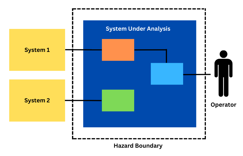
While this works well with clearly defined interfaces between the system under analysis and systems 1 and 2, it can lead to oversimplification of the interface with the operator. As such, the system safety engineer will often either simply consider the operator as another deterministic system which will always respond in the same way to an output or will ignore the operator assuming they are fully competent to perform the task at hand. In reality the ‘operator’ in this example will have a much more complicated response and their input or reaction to an output of the system under analysis will depend on a wide range of factors.
One way to tease out these nuances and better understand how the ‘operator’ will respond to the system under analysis is to conduct a human reliability analysis for the activities where the system under analysis relies upon the ‘operator’ to correctly function. In doing so the system safety engineer is effectively re-drawing their system under analysis and hazard boundary to include the ‘operator’ (see Figure 2).
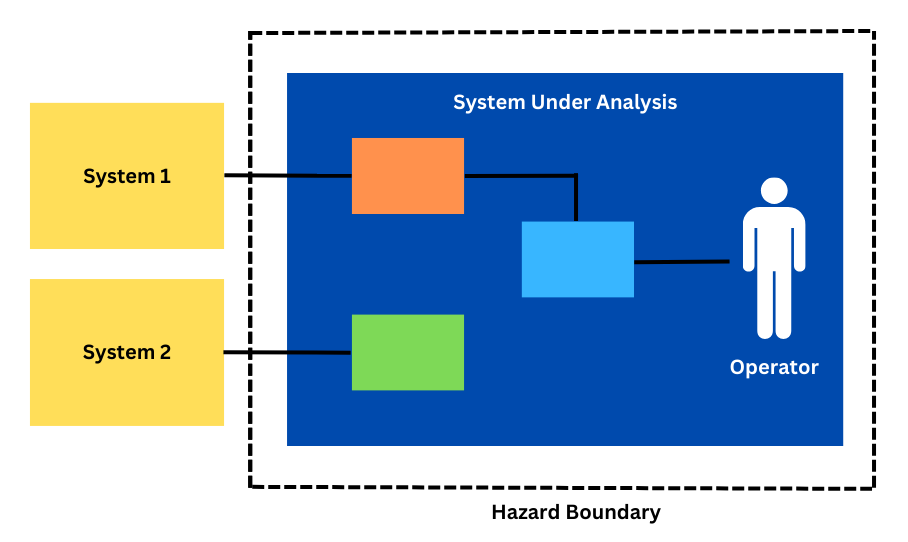
This is especially important where the human is a part of the overarching function of the system, such as in a control system, where they are presented information and indications and then provide commands for the continued operation of the system under analysis.
What is Human Reliability Analysis?
Human Reliability Analysis (HRA) techniques, or human reliability techniques, are methods used to assess human performance within a system and to derive a quantitative probability that a human will correctly execute the task(s) required of them.
When do you use it?
An HRA can be used in scenarios where:
- Human performance is critical in the safety function being assessed.
- A quantified safety analysis is being performed that requires a probability assigned to the human contribution.
- Human centric processes are being developed or changed and there is a need to assess any negative impacts on system performance.
However, as an HRA can be quite time consuming and challenging to perform, the authors recommend only using HRA when needing to quantify human reliability in high-risk scenarios where humans must perform an action which may have safety-critical outcomes.
If a safety system fully protects the operations of the human, the need for an HRA diminishes. For example, an HRA would have limited use to support the design of a train control system where a interlocking prevents the train controller setting the wrong route at the controllers’ interface. However, an HRA could be useful to support the design of a system where the operator can bypass a safety function, such as performing an axle counter reset.
What are the Options?
There are several methods available to the systems safety engineers and human factors practitioners needing to perform an HRA. These methods include:
- Cognitive Reliability and Error Analysis Method (CREAM) (Hollnagel, 1998)
- Human Error Assessment and Reduction Technique (HEART) (Williams, 1985),
- Systematic Human Error Reduction and Prediction Approach (SHERPA) (Embrey, 1986), and
- Technique for Human Error Rate Prediction (THERP) (Swain and Guttman, 1983).
These techniques provide a framework to understand how and why errors occur and what factors make errors more likely. In the rail industry the United Kingdom’s Rail Safety Standards Board has produced a Railway Action Reliability Assessment (RARA) based on HEART which is tailored for the rail industry (Gibson, 2012).
How do you do it?
Regardless of the technique or method chosen, the first step required is to fully understand what tasks or activities the human performs within the system. This is often done through performing a task analysis (Shepherd, 2001).
Second, the analysis needs to identify any environmental factors the human may be exposed to when performing the task, for example:
- Will they be under time pressure?
- Is the activity routine or an emergency response?
- Is the activity clearly laid out in a procedure? Or does it require on the fly decision making?
- Are they highly trained? Or are they unfamiliar with the activity?
- What is the physical environment? (e.g., hot, cold, low light, high noise, etc.)
Noting that depending on the activity, not all these factors may be known (i.e., when analysing a new system rather than assessing an existing system) and, as such, any assumptions made need to be clearly captured and communicated.
The third step is working out where and how a person can fail while performing the tasks in the task analysis and which of these failures might contribute to the undesired or hazardous outcomes the system safety engineer is assessing.
Fourthly, the probability of that failure should be estimated using the selected technique (see above).
Where do we use it?
The results of an HRA can then be used by a system safety engineer for activities including:
- Quantifying the probability of a human failure contributing to an undesired event modelled in a Fault Tree Analysis (FTA),
- Quantitatively comparing the human error contribution an event sequence when performing an options analysis, or
- Identifying appropriate safety controls to mitigate against human error.
The case studies in Sections 4 and 5 will explore using an HRA in these contexts.
Case Study 1: Tunnel Ventilation System
On a recent project, the authors have worked on a completely new control system was introduced into an operational railway control room. This new system operates a Tunnel Ventilation System (TVS).
The TVS plays a key safety role in providing airflow in the event a train is on fire and stopped in the tunnel. The Tunnel Ventilation Operator (TVO) has the responsibility to make sure the TVS is correctly activated for the train on fire scenario. An HRA was undertaken to fully understand the human error probability contribution to the system failing to activate a correct TVS ventilation mode.
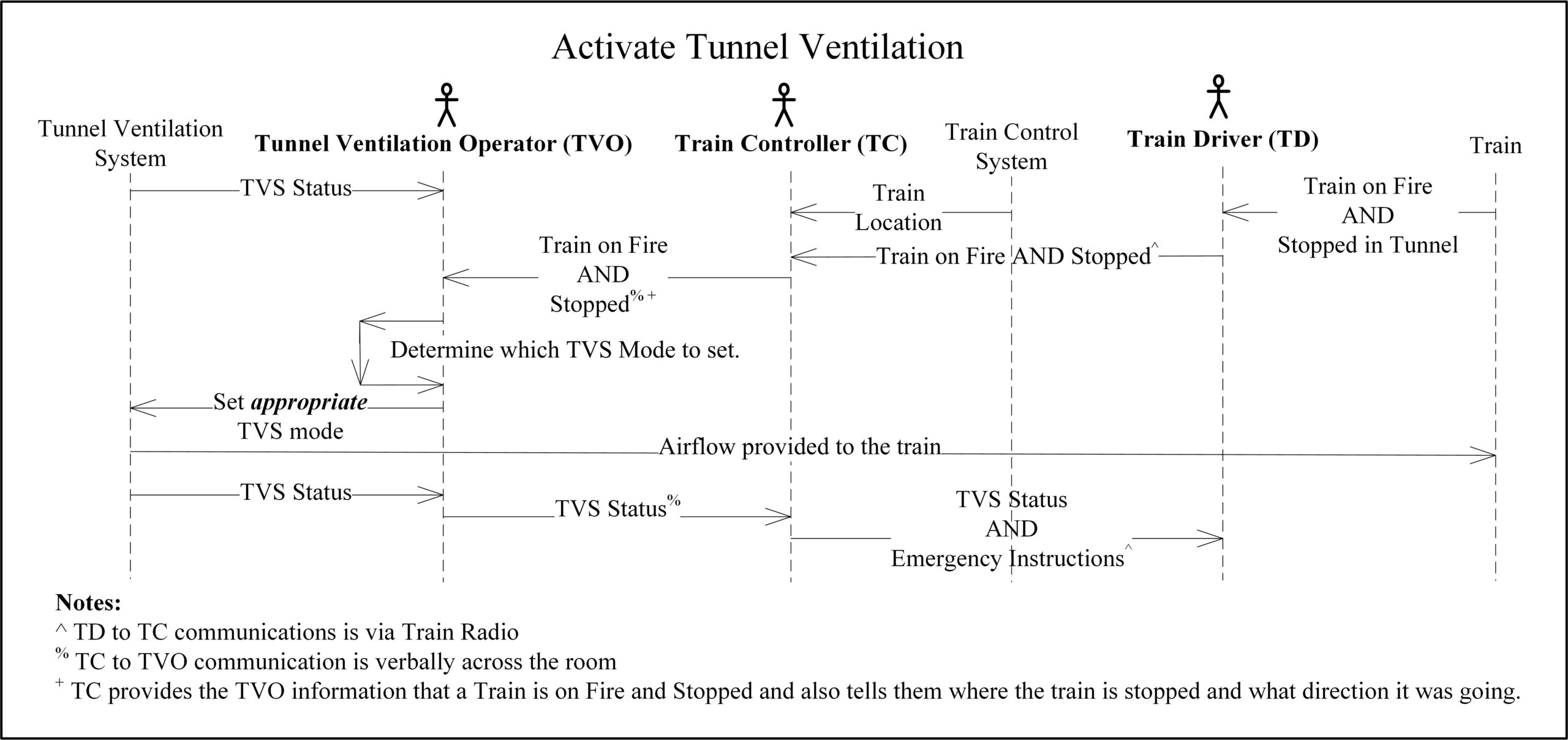
Fig. 3: Tunnel Activation Control Sequence Task Analysis
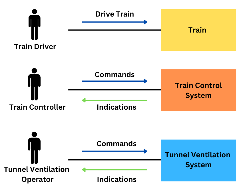
The authors first completed a task analysis for the scenario of activating the TVS during a train on fire event. Given this was a new system introduced to the rail operator, the task analysis was based on the expected tasks, rather than actual observed tasks. This was envisioned to involve three operators, the (Tunnel Ventilation Operator) TVO, Train Controller (TC), and Train Driver (TD) as depicted in Figure 4.
The task analysis identified several steps which required transfer of information between people (via train radio or in-person communication within the same control centre):
- TD reports the train fire (and location of the fire on board the train) to the TC via train radio,
- TC reports details of the incident to the TVO,
- TVO communicates the status of the TVS to the TC, and
- TC reports status of the TVS to the TD and gives instructions on emergency response.
This chain of communication introduces the potential for error, including communicating incorrect information or misunderstanding information. It also introduces delay to implementing the safety critical function of smoke extraction.
The task analysis also identified an important step of the TVO selecting the appropriate ventilation mode on the Tunnel Ventilation interface. This step involves:
- A critical decision of which ventilation mode to apply, and
- Selecting the appropriate mode on the TVS interface.
This step will be performed by the TVO while under time pressure and stress. It will likely be an unfamiliar event which the TVO has never encountered, except during training or maintenance of competence. These steps are depicted in a sequence diagram captured in Figure 3.
HRA – Manual Control
Potential errors were then identified for each step of the task analysis. Some examples of the errors identified include:
- TD fails to detect the fire alarm on board the train,
- TD fails to communicate the fire event to TC within the required time frame,
- TC misunderstands the information provided by the TD,
- TC communicates incorrect information to TVO,
- TVO misunderstands the information provided by the TC,
- TVO decides to operate the incorrect tunnel ventilation mode, and
- TVO selects the incorrect mode on the TVS interface.
The authors applied the RARA methodology to calculate the human error rate for each identified error. RARA applies the following steps:
- Identify the unreliability type for the Generic Task Type (GTT) (each type has an associated unreliability score),
- Identify the error producing conditions (each error producing condition has an associated maximum effect),
- Assess the proportion of effect of each error producing condition on the task from 0 to 1 (estimated effect),
- Calculate the assessed effect, using the formula [[(maximum effect – 1) x proportion of effect] + 1], and
- Calculate the Human Error Probability (HEP) using the formula [GTT x assessed effect].
The resulting calculations for each of the seven example errors identified above are shown in Table 1.
Note that the human error probabilities calculated in Table 1 are highly conservative. The main purpose of this analysis was to identify significant contributions to risk, rather than definitively calculate human error rates. However, the calculation of conservative human error probabilities were still able to be used to calculate an overall conservative estimate of the undesired event probability (i.e. failure to activate the correct tunnel ventilation mode).
These HEPs were used as estimates of human failure in a fault tree analysis. This is illustrated in Figure 5.
The HRA showed that the TVO deciding to take the wrong course of action was the key contribution of risk (Error 6, Human Error Probability = 0.416). This error could result from the TVO misunderstanding or mishearing information reported from the TC, or the TC reporting the incorrect information (which, in turn, could be from the TC misunderstanding or mishearing information from the TD). Alternatively, this decision error could occur because the situation is unfamiliar to the TVO, and they did not know what the correct course of action was.
Manual vs Automatic Control
One of the key benefits of conducting an HRA is that it helps identify the types of errors that contribute to risk, and therefore the types of controls that can mitigate against the risk. In this example, the key contribution to risk was:
- Potential communication failures between the TD, TC, and TVO; and
- The TVO setting the incorrect ventilation mode.
A key contributor to communication failures was the chain of communication between the TD, TC, and TVO. A solution considered, but rejected, was to provide a method of direct communication between the TD and the TVO. While this would minimise the need for the TC to relay information between the TD and the TVO, it introduces the risk of the TC being unaware of safety critical information and it does not comply with the operational requirement of the TC to be the TD’s point of contact (and therefore, may introduce confusion).
Rather, to reduce the reliance on the operators transferring information, a recommendation was made to add an automatic signal between the fire systems onboard the train to the tunnel ventilation control system. Note that this automatic signal did not replace the expectation of communication between the operators but acts as a backup to minimise the risk of communication failures.
The TVO setting the incorrect ventilation mode is likely to occur because the situation is novel and will occur under a high time pressure situation, increasing the chance of the TVO making the wrong decision. To minimise the risk of a decision error, the recommended solution included the TVS displaying a suggested ventilation response. The TVO needs to review and confirm the suggested response within a specific timeframe before the suggested response will be automatically activated (by the system) if no response is provided. This also controls for the risk of the TVO not being at their desk during the emergency event.
HRA – Automatic Control
Considering the inclusion of the automatic control, the human error probability of the TVO could be revisited. Table 2 provides a reassessment of the HEP for errors 5 and 6.
These can be plugged into a modified Figure 5 to calculate an updated overarching probability of the undesired event as shown in Figure 6. Noting that having information from an independent source allows the TVO to cross check the information they receive from the TC to question its correctness and effectively halve the risk.
However, it should be noted that the additional task of the TVO confirming the suggested response may introduce the following 3 errors:
- The TVO fails to cross check (clears the prompt without cross checking). This may be a result of the TVO trusting the suggested response (and not thinking that they need to cross-check), or because multiple prompts and alarms are generated and the TVO is used to clearing the prompt without cross-checking information.
- The TVO cross checks but incorrectly disregards the suggested response. This may occur because the TVO does not have enough information about the situation to make an informed decision.
- The TVO cross checks but incorrectly accepts the suggested response. This may occur because the TVO does not have enough information about the system to make an informed decision. Or because the TVO trusts the suggested response, despite it conflicting with the other information.
Takeaways
Reflection on this first case study of how an HRA was used to assess the implementation of a TVS into a railway control centre identified the following takeaways:
- The primary benefit of the HRA was to show that operators were a significant contribution to risk. As a result, this HRA was a key input into the FTA and was used to drive design change.
- The HRA in this example was predictive as the system is not yet in use. Predictive HRAs come with the caveat that the calculated HEP may be higher or lower in practice. The authors took a conservative approach to calculating the human error probabilities. This conservatism was applied consistently across the analysis, including both original ‘baseline’ system and when evaluating the different design solutions.
- Related to point 2, rather than focusing on the exact number which has been calculated, HRAs allow the analysts to identify what actions contribute the highest risk, and therefore, the parts of the system which require further attention. This may include ranking the human errors in order from most likely to occur to least likely to occur.
- The identification of the types of errors can help identify risk controls to mitigate that type of human error. This is important as it allows the project team to direct effort and resources towards mitigations which will have the most significant impact on risk. In this case, having a chain of communication through three different operators to perform a safety critical task was identified as potentially introducing compounding errors, which could be mitigated by the introduction of an engineering control.
- The HRA can also help when comparing multiple design solutions and risk controls to identify which combination provides the greatest risk reduction for the operator.
Case Study 2: New Train Control System
On several past projects introducing new train control and signalling systems that the authors have been involved with, the new systems were required to demonstrate that the delivered system achieved an overarching tolerable hazard rate. As the safety analysis identified that there were several scenarios where an operator contributed to the undesired events, an HRA was performed to quantify those failure modes.
Scenarios
A sub-set of the scenarios identified on these past projects that involved an operator include:
- Standard railway controls (e.g., setting routes and swinging points) (see below),
- Safety bypass controls (e.g., emergency route release or call on), and
- Remote Axle Counter Resets and Sweep Bypass (see below).
Standard Railway Controls (Scenario 1)
Traditional signalling systems replicate the simple architecture shown in Figure 7.
As shown in Figure 7 the operator plays a key role in monitoring the status of the railway and setting routes for the trains. A standard route request will typically follow the logic sequence shown in Figure 8.
In the traditional system, the signalling interlocking’s primary function is to use the inputs it receives from track circuits or axle counters (vacancy detection) and check if the route being requested by the operator is available (i.e., not already set or occupied by a train). If it is occupied or already part of a set route, the interlocking will prevent the route from being set. In such a scenario the safety of the system primarily rests with the signalling system and not the operator. Though for completeness, the human error probability for these standard scenarios can be estimated.
Safety Bypass Controls (Scenario 2)
On one project the train control and signalling system was required to implement several safety bypass functions which in certain scenarios could bypass the checks being done by the interlocking and thus rely heavily on the operator to ensure the safety of the railway. These included a:
- Call on function which allows the operator to set a ‘call on’ signal which indicates to the train driver that they can proceed past a signal set at danger (i.e., red) and enter a route that may be occupied (i.e., the signal has not cleared). This may be due to failed equipment such as a track circuit or axle counter failing to clear or a signal failure.
- Emergency route release which allows the operator to ‘clear’ a route that has not released after a passage of a train due to equipment failure.
- Points emergency which allows the operator to swing a set of points even if the track circuit across the points are occupied.
Figure 9 captures this control sequence.
Unlike the standard railway controls, each of these safety bypass controls require the operator to take the responsibility for confirming the track is clear and it is safe to perform one of these safety bypass functions. To prevent spurious activation of these controls which will bypass the interlocking functions, the train control system required a password from the operator to initiate the bypass, and then the interlocking required the train control system to provide the request and a second confirmation from the operator within a set time frame to accept the request.
To further reduce the safety risk for a ‘call on’ event the driver is required to proceed past the ‘call on’ at slow speed and be ready to stop if the section is occupied. For the emergency route release, it can only be released if a timer has expired that considers the length of the route and the expected time it will take to traverse the route.
For the points emergency, procedurally, the points must visually be confirmed by the local train control operator to not have a train across them before they are swung using the points emergency control.
Finally, the operator is required to log each use of the safety bypass control and their rationale for the action taken. This physical log is audited by the railway authority and compared to the train control system’s own digital logs for the frequency of use. This is done to prevent unnecessary overuse of the safety bypass controls.
Due to the key role the operator plays in deciding it is safe to bypass the interlocking in these scenarios, it is important for the system safety engineer to understand the probability of human error in using these controls.
Axle Counter Reset Controls (Scenario 3)
A second project was implementing axle counters for the first time and required a mechanism for remote axle counter resets, for bypassing the subsequent ‘sweep’ requirement, and resetting an axle counter after a hi-rail vehicle either enters or exits the network.
An axle counter counts in each axle of a train into a section and then counts those axles out as depicted in Figure 11.
When an axle counter fails to count a train out of a section (see option A in Figure 12) or it over counts the axles out of a section (i.e. more axles are counted leaving a section than enter it) (see option B in Figure 12) the axle counter needs to be reset.
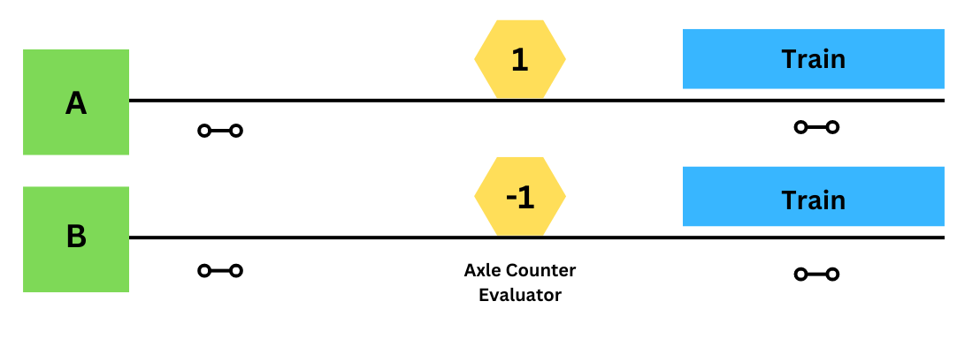
A common way to reset an axle counter is to send a technician to site to visually confirm there is no train present on the track and to locally reset the axle counter. However, due to the operational impact of sending a technician to site a remote reset option may be required, especially, where there is an on-tracking pad in the axle counter section where a high rail vehicle may enter the section without counting in and thus resulting in a negative count when entering the network and a positive count when exiting it. This reset control sequence is captured in Figure 10.
Due to the operator involved in this decision making process, that resets a critical safety function (vacancy detection), it is important to consider the human error potential involved in implementing this function.
HRA
Each of the scenarios described above require an HRA to determine the contribution of people in the system when performing these safety functions. In each of these scenarios, the human error probability is estimated, and its contribution considered in a fault tree analysis to understand its contribution to the overall undesired event.
Standard Railway Controls (Scenario 1)
In Scenario 1 (see above), the operator is required to understand the state of the railway from the indications provided and to set routes for trains to accomplish the train movements required by the organisation’s timetable. The operator then can make an error by misinterpreting the indications provided or by simply requesting the wrong route.
A human error probability was estimated for this scenario using the RARA. A GTT of R4 or R6 was conservatively selected and, for the purposes of this assessment, the error producing conditions (EPC) were assumed to be non-existent (noting if a less conservative GTT has been selected (e.g., R1 or R2) a more detailed assessment may be appropriate). Therefore, using a human error probability of 3e-3 was applied to the human error contribution in the fault tree depicted in Figure 13.
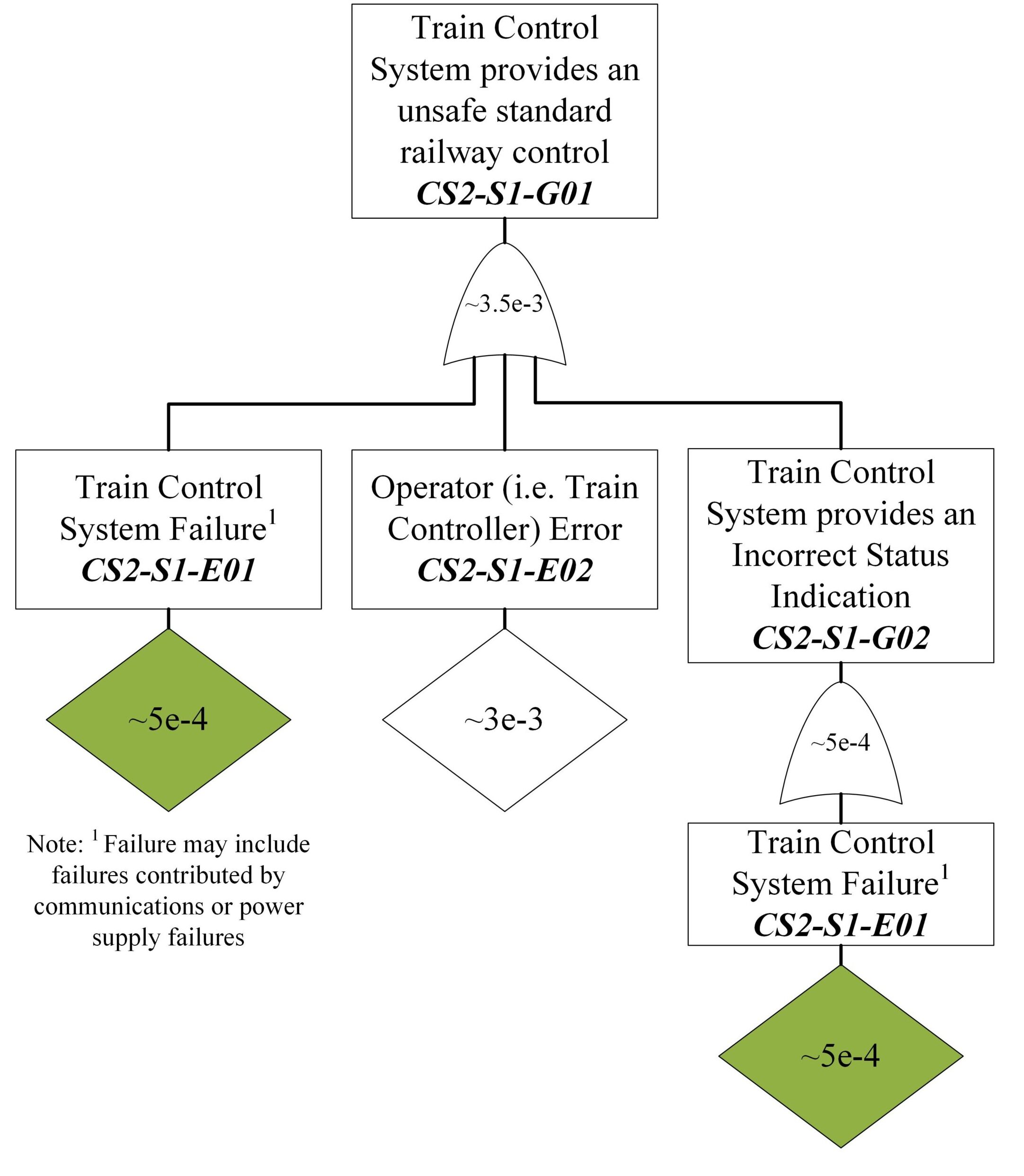
As such it can be shown that the human error is likely to be the primary contributor to the train control system sending an unsafe standard railway control to the interlocking and that significant additional work to increase the integrity of the train control system is likely to be unnecessary. Note that in this scenario, all the standard railway controls are checked by a high integrity interlocking which will prevent an unsafe action from being implemented.
Safety Bypass Controls (Scenario 2)
Scenario 2 describes three safety bypass controls, each of which require the operator to confirm it is safe to implement a safety bypass function. To illustrate the use of HEP, the contribution of the operator to an unsafe points emergency operation was considered.
Again, a human error probability was estimated for this scenario as was done in Scenario 1 (see below). As such a human error probability of 3e-3 was used as shown in Figure 14.
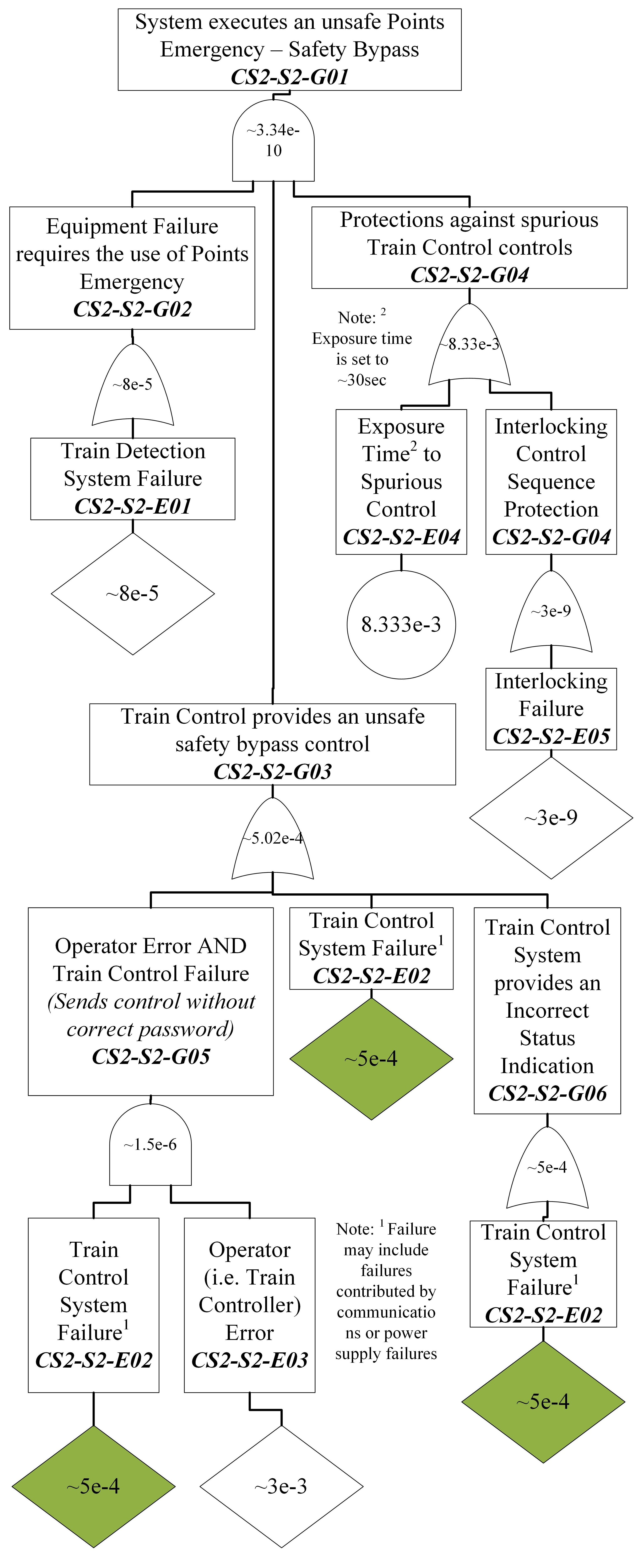
As seen in this scenario, the use of a password and subsequent confirmations required by the operator ostensibly means that the primary concern and contributor to this event is a spurious control from the train control system which is mitigated by the interlocking requiring the dual controls to come in within a thirty second period.
However, if these engineering controls were not implemented, the human contribution to the undesired event would play a key role and a much more extensive HRA may be required. This is especially true considering these safety bypass functions are required to mitigate infrequent occurrences that may involve operational pressure to keep the railway running. Noting that involving a second operator (e.g., a supervisor) may have had additional benefit in reducing the risk; however, on this project a supervisor was not available at the remote stations.
Axle Counter Reset Controls (Scenario 3)
Scenario 3 (see above) looks at the operator involvement in resetting an axle counter after a miscount. In this scenario, as a mitigation to a single human error each reset mechanism requires the involvement of at least two people. In the standard axle counter reset after the operator triggers the reset the human train ‘driver’ takes the train slowly through the affected section ready to stop in the event they see an obstruction (e.g., another train on the line). The sweep bypass and hi-rail entry/exit reset both require the involvement of a maintainer in addition to the operator.
On this project a human error rate was derived from THERP using a nominal human error probability of 3e-3 considering an operator failing to carry out a step in a complex procedure given that a correctly written procedure exists and is used. Figure 15 illustrates the use in estimating the probability of an unsafe axle counter sweep bypass.
Like Scenario 1 (see Section above), the human error probability is higher than the failure probability of the control panels but in this case the safety of the system is not protected by interlocking rules as this function effectively creates a blank slate of the network with all tracks being determined as vacant. This highlights that great care should be taken when initiating and using this function and raises the question whether a better engineering solution may need to be investigated.
For this project, the function of a ‘sweep bypass’ was only to be used when re-opening the railway after a closure and the procedure required staff onsite to confirm to the operator and maintainer than the tracks are in fact clear prior to the sweep bypass being activated. As such the primary concern was focused on its spurious use which can be prevented by disabling the maintenance panel.
Takeaways
Reflection on this second case study of how system safety engineers have used the results of an HRA in the past identifies the following takeaways:
- A detailed HRA may not always be required. A simple ballpark estimate may be sufficient in some circumstances. However, even so, for the operator to achieve the ballpark estimate requires the operator to follow good procedures, be trained and to be competent for their tasks at hand. It is important to ensure that the work done is in line with what is planned (i.e., in the procedures).
- All the scenarios identified in this second case study would have benefited from having more input from a human factors specialist to better tease out how the human interacted with the system. In each of these, more work should have been done to better understand how the human contributed to the undesired event even if the error probability did not significantly change.
- Considering human error in the safety analysis can identify the need for engineering controls to reduce those errors. Involving human factors early in the design process increases the chance the engineered solution will actually be able to reduce human error and not in themselves add further risks (e.g., implementing double controls, using passwords, display layouts, …).
- Considering the human in the system can help the systems safety engineers to not lose themselves in the allocation of integrity levels to equipment when the highest benefit would come from improving the reliability, reducing the reliance on, or even removing the human in the system.
- Not all scenarios necessarily will call for a full HRA and as a full HRA can be quite time consuming it is important to focus the limited resources on where it will make the greatest impact. For example, a detailed task analysis and HRA is not needed for standard railway controls; however, the safety bypass functions could have benefited from a more detailed task analysis and a deeper understanding of the scenarios when the function would be used to understand how best to mitigate the risk posed.
Conclusion – How Useful is it?
In conclusion quantifying human reliability in safety analysis is useful in:
- Helping to show the potential human error contribution to an undesired event,
- Identify where a system is vulnerable to use errors, and
- Highlighting areas where system design could be improved to remove the sources, minimise the impact, or reduce those probability of those errors.
The key to uncovering its usefulness is to appropriately identify which human activities are critical to assess, as not all user error scenarios warrant detailed quantification and assessment. It is not all about the ‘number’ it is about understanding what kind of human error may occur and identifying what can be done to eliminate, prevent, mitigate, or reduce the risk the error occurs. If the error is a knowledge-based error than a control may be training. If the error is a decision error, then a mitigation may be to provide additional decisions support aids.
The following principles and caveats attempt to provide system safety engineers and human factors specialists guidance when using an HRA.
Principles
When quantifying human reliability in a safety analysis remember the following key principles:
- Keep it simple / do not over complicate it.
- Focus on areas of higher risk.
- Engage with a human factors specialist and ideally end users to be able to characterise the human error potential.
- Clearly justify the human error probabilities used (i.e., show your work and explain your choices).
- Make sure that you understand what the human is going to be doing and how they understand the activities (i.e., do a task analysis) and document it.
- Focus less on the number but on what can be done to reduce the risk (e.g., to control for the risk of an operator forgetting to complete a task, can we introduce a prompt as a reminder?). Risk mitigation is not only about reducing the likelihood – it also includes minimising the consequence. Focus on what can be done to help operators and users avoid using the system incorrectly.
- If estimating a human error probability, use an appropriate HRA technique. For example, using RARA is a good choice for the rail industry.
Caveats
While it is important to remember the key principles it is equally important to remember these caveats:
- Do not get caught up in the number (it is just an estimate). Justify it and move on.
- Be careful with quantified human error probabilities as it can be easy to be overly conversative or too optimistic which can lead to poor decisions.
- Be wary of arguments that rely on multiple humans to check and cross check. Unless the right procedures and rules are in place and followed the there is a risk that either the first person will be influenced by the other or that one person may bypass the other.
- Remember to use common sense. If the result of the HRA does not make sense, it probably is not correct, and the assumptions and inputs should be revisited.
- The use of an HRA does not in itself demonstrate the reduction of risk so far as is reasonably practicable. The HRA is only one element in the overarching safety argument.
Keryn Pauley & Andrew Gabler
Related Content: How to Argue Risk is Reduced SFAIRP
References
- Embrey, D.E. (1986). SHERPA: A systematic human error reduction and prediction approach. United States: American Nuclear Society.
- Gibson, H. (2012): Railway Action Reliability Assessment user manual – A technique for the quantification of human error in the rail industry. T270. RSSB. London.
- Hollnagel, E. (1988). Cognitive Reliability and Error Analysis Method (CREAM), 1st Edition. Elsevier Science. Oxford, England.
- Shepherd, A. (2001) Hierarchical Task Analysis Taylor and Francis: London.
- Swain A. D. and Guttmann H. E. (1983): Handbook of Human Reliability Analysis with Emphasis on Nuclear Power Plant Applications – Final Report. NUREG/CR-1278, NRC.
- Williams, J. C. (1985). HEART – A proposed method for achieving high reliability in process operation by means of human factors engineering technology. In Proceedings of a Symposium on the Achievement of Reliability in Operating Plant, Safety and Reliability Society, 16, 5/1-5/15.