Hazard logs are at the core of any system safety argument or safety case. This article explores some of the challenges with the standard tabular, textual hazard logs and whether these challenges can be addressed with support from Model Based Systems Engineering (MBSE).
In this article, we will:
- Identify several challenges faced by system safety engineers with existing hazard logs.
- Look at several existing methods used to over come these challenges.
- Consider how MBSE using Systems Modelling Language (SysML) tools may be able address those challenges.
The Challenges of Using Hazard Logs
The standard hazard log, following industry standards such as EN50126-1 [1], captures hazards in a tabular, textual form using a large spreadsheet or assurance database (e.g. IBM DOORS Next). These spreadsheets and data bases are often customised in a format to comply with relevant standards and/or a stakeholder’s templates for on-going safety risk management.
Although this approach is widely used, it does create a few notable challenges:
- Challenge 1: It takes specialist knowledge to understand them. Text-based formats do not intuitively demonstrate the causal relationships between hazards, causes and controls to those who are unfamiliar with system hazard analysis and risk assessment processes in general.
- Challenge 2: It takes a significant amount of time from specialist safety engineers and other stakeholders to prepare, manage, maintain these hazard logs at a high level of quality and prepare explanations to stakeholders.
- Challenge 3: It is difficult to demonstrate the completeness of the hazard log (required for a solid SFAIRP argument) showing that all safety-related functions/data flows between different sub-systems have been analysed.
How Can We Resolve These Challenges?
There are several methods commonly used that attempt to resolve these challenges. These are examined below.
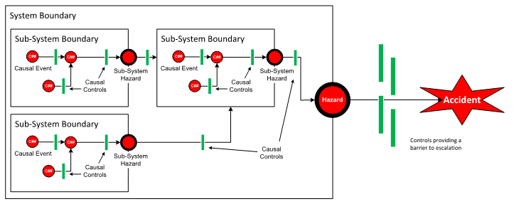
Illustrate Hazard Analysis with Diagrams
Visualisation of the hazard, causes, controls and other architectural relationships as shown in Figure 1 enables non subject matter experts to understand the hazards intuitively and in part solves the issues identified in Challenge 1.
This approach is appropriate when the quantity of information is limited; however, might not be cost-effective when attempting to illustrate a wider scope due to the amount of time and effort required to produce such diagrams (Challenge 2).
As the complexity of a system increases, a diagram of this type can become very costly to create and manage using conventional drawing tools, such as Microsoft Visio. Tools such as Visio lack integration (or have limited integration) between the diagram and data analysis tools such as a spreadsheet or a database.
Safety engineers are subsequently required to expend effort processing information in the diagrams and transferring it to a spreadsheet or database which can be prone to error. As a result of these deficiencies, such diagrams are not commonly produced unless required by very specific project requirements or to illustrate a specific, novel risk assessment.
Systematic Analyses and Subject Matter Expert Reviews
Current best practice is to execute techniques and methods for safety analyses such as those defined in Table F.2 of EN50126-2:2017 [2]. These techniques and methods are coupled with cross-functional reviews by subject matter experts, systems engineers, human factors specialists, safety engineers or field engineers. These cross-functional reviews help to ensure that all possible hazards, causes and controls have been identified and documented in the hazard log.
This method is a plausible solution for Challenge 3. However, as the size and complexity of the system increases, so too does the quantity of information covered in the safety analyses. This results in a proportional increase in time spent by reviewers (Challenge 2).
How Can Model Based Systems Engineering Help?
MBSE allows systems engineers to define the system under analysis in a model that defines the physical and functional blocks of the system and the interactions between those blocks and other systems. A well-modelled system then provides all the information required by a safety engineer to perform their traditional safety analysis techniques.
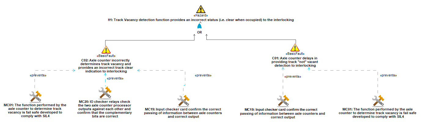
The concept considered here is to enhance the traditional model-based diagrams with hazard, causal, and control information to provide a view that overlay the hazards, causal links, and controls on the system model as shown conceptually in Figure 2.
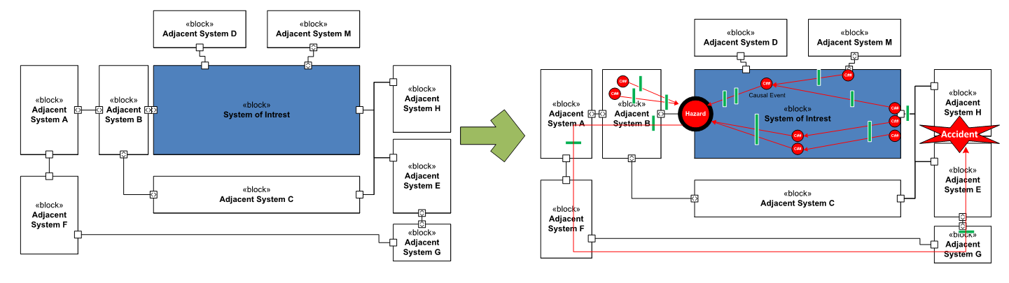
By linking the hazard analysis and results to the complete model it can then be easily shown that the hazard analysis is complete (Challenge 3). The pictorial view of the hazard flow with causal linking and identified controls can enhance the readability and understanding of the analysis for stakeholders (Challenge 1) reducing review time (Challenge 2).
The MBSE tooling will provide the safety engineer a single model to work in and coupled with automated report generation will reduce the time it takes to perform the model and increases the potential for re-use (Challenge 2). This concept has attracted the attention of industry experts and researchers who have made great efforts to standardise the process of integrating safety analysis into MBSE and extend the capability of the MBSE toolbox to support this process [3].
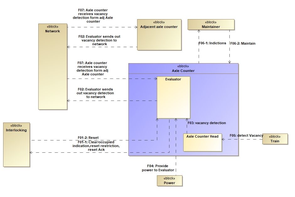
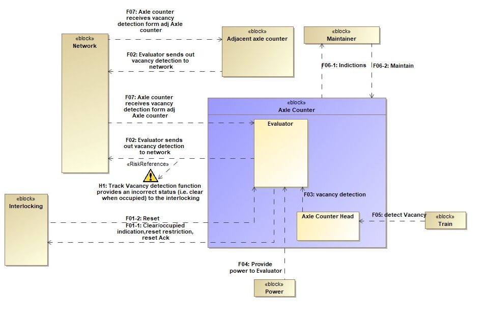
Implementation
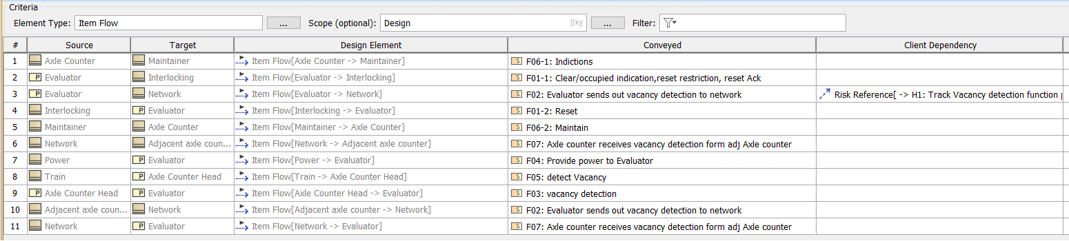
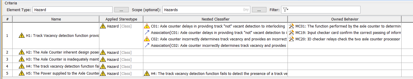
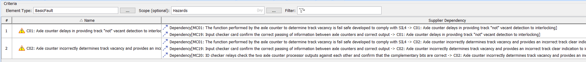
This concept was explored using the MBSE tool* “MagicDraw” to create a model for a simple axle counter system. The activity found that while promising there is still more work required in improving the tool set to fully realise the advantages envisioned in the concept.
This implementation is captured in the series of diagrams (Figures 3-8) featured below.
*There are a number of MBSE tools available, including IBM Engineering Systems Design Rhapsody Architect, Cameo Systems Modeller (MagicDraw) and Capella.
Conclusion
There are a number of challenges faced by safety engineers in communicating hazard logs to stakeholders (Challenge 1), improve efficiency of preparation and maintenance of hazard logs(Challenge 2), and demonstrating completeness of the hazard log (Challenge 3).
It has been shown that MBSE has a significant potential to aid safety engineers in collaboration with systems engineers,overcome these challenges; however, there still exists some challenges to fully realise this.
Acmena will continue to research how to better use the tools made available through MBSE to improve the efficiency and strength of their safety arguments.
Andrew Gabler, Dan Munoz & Ya’ nan Li
Related Content: What is a Hazard?